This document applies to the setting up of projects involving PD 3950 USB and/or PD 664 GRPS modules. Both these communicating type modules require the functionality provided by networking software running on a local or remotely located PC, called the P-NET Gateway Service. It describes how to configure the Gateway Service to suit any project, no matter whether it consists of several modules of the same type, or a mixture of both types.
P-NET Gateway Service Editor
The Service Editor will be installed along with VIGO.
The purpose of this utility program is to provide the means for a user to establish a communication link between this PC and one or several devices of the types PD 3950 or PD 664 via a PC running the P-NET Gateway Service

When the Editor is running, it will dynamically monitor VIGO in terms of identifying any active projects defined as involving the Gateway Service. In other words, within a given Workspace, any selected project defined as including one or more Gateway Service UDP or TCP modules will be recognized by the editor and counted. This is displayed in a ‘Summary’ on the first line of the Editor as ‘No. of nodes:’ Similarly, the number of UDP/TCP type nets (IP-v2, neighbour) are also counted and shown as ‘No. of nets:’
Below this will be displayed as a list, UDP modules that have been identified in any of the selected projects. These represent the communication interface between this PC and the P-NET Gateway Service and requires a specific service to be configured to run. So, if two projects are selected, for example, the provided GPRS and the USB projects, each will be listed as a separate service. This list is also reproduced in the pull-down list at the top, where a selection can be made. Configuration of the selected service is started by clicking the ‘Configure’ button

N.B. It must be ensured that ‘This PC’ (Vigo PC) in the workspace is attached to the same net as that defined for the UDP software module included in the service being configured. If it is not, a message such as ‘No response, Timeout’ or ‘Netname not found’ or similar will be seen. Extra care is required if the P-NET Gateway Service is being run on another PC within a local area network or via an Internet connection, to ensure that a basic link is open. If modifications to a previously configured service have been made, then reconfiguration will indicate details of the last one, with an opportunity to confirm the change.
Using the selected example USB project locally without any changes or additions should work without configuring the service. Initially, and following any changes to a previously configured project service involving the gateway modules, where the required service is itemised in the editor as including a UDP type gateway module, must have the configuration run again, otherwise any restored communication may not operate as expected.

In summary, here is a step by step guide to configuring a local Gateway Service for USB communication. Just follow these steps to run it:
1) Using the default VIGO configuration as an example, ensure that the USB project has been selected in the VIGO workspace.
2) Start the Gateway Service Editor software on the VIGO PC, using this path: Start button \ All Programs \ PROCES-DATA \ P-NET Gateway Service\ P-NET Gateway service editor.
3) Select the service from the “List of services”. Projects that are recognized by the configuring editor are those enabled in the workspace and which include one or more UDP service modules linked with other gateway type software modules.
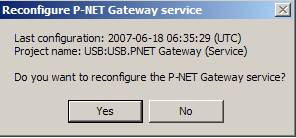
4) Press ‘Configure the selected service’. A warning message appears, asking whether you actually wish to reconfigure the service (first picture).
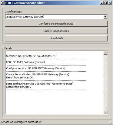
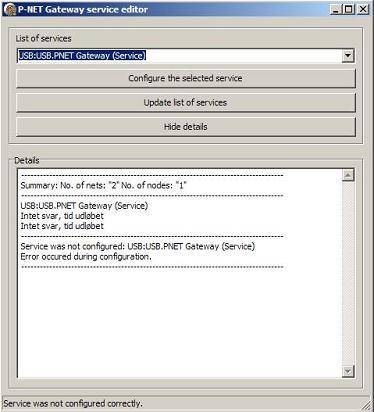
5) By confirming the action, the reconfiguration is run. The outcome can be seen in the details window. At the bottom of the window, a message will show whether the service was configured successfully (second picture), or if the action for some reason was unsuccessful (third picture).
As well as being able to select the editor itself, the Gateway Service section in VIGO also offers the choice of starting and stopping the service.
Once installed, the service starts automatically when the computer starts, so normally the user doesn’t have to be concerned about this.
If, for some reason, the service has been accidentally stopped, no communication will take place, and furthermore, the service editor procedure cannot be run. The outcome will be “No answer, time out”, and on the bottom line a note showing that the service was not configured correctly (third picture, in which a few of the lines in the details window is in Danish).
There may be situations where the configuration of the service is unsuccessful and error massages are displayed. Some of these may be associated with basic communication such as ‘Time out, no response’ or ‘net name not found’ etc. In these cases, it should be ensured that basic communication channels are open, especially in the case of remotely located Gateway Service PCs (See link tests described in the GPRS Tutorial). Also that the link between ‘This PC’ in the workspace uses the same named net as that defined for the associated UDP module, and that the UDP module IP address is correct and has the correct port number association. If a secure UDP net is being used, it must also be ensured that the Key Manager and Key Generator have been used to initially set up the secure link.
Other messages may provide a clue as to the problem such as “Object already in configuration” or “Possible loopback error in MIB”. This means that it is likely that the structure of a project in terms of the utilization of named nets and modules is incompatible with that expected by the Gateway service. This may also show up in an incorrect expected count for the number of communication hardware/software modules and associated IP and neighbour nets. Whilst it is perfectly feasible to structure a complex project incorporating a number of GRRS modules and UDP modules, it is very important that the ‘basic’ structure of grouping (in folders) gateway modules, communication modules, nets and VIGO PCs, into recognizable ‘services’ as shown in both the example GPRS and USB projects, is adhered to.
When the gateway service is running correctly, the green On LED should be lit and the green Link LED should be flashing. Please consult the LED indicators for further details.
When trying to access the PD 3950 for the first time without success, it may be necessary to stop and start the service.
Refer to the P-NET Gateway Service page if further information is required. This would, however, only be necessary in cases that differ from the one described here.
