PD 620 Application Note - Overview
Feature overview
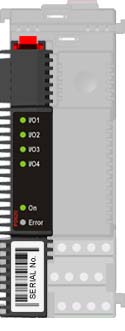
The PD 620 contains 4 channels, each of which can be independently configured as a digital input or digital output.
The PD 620 actually measures the voltage on an input/output pin, which means that a channel can be utilised as an analogue input.
Because of local intelligence within the PD 620, each input or output channel offers advanced functionality. These functions are integrated into the module itself and need only to be configured for operation, so no additional programming is needed. In fact, these unique functions can save a great deal of programming effort.
Since the functions and safety monitors are embedded in the module, they execute independently of external controllers. This ensures safety, ultra fast response and independence from system reaction time.
All PROCES-DATA modules are based on the channel concept. A channel is a functional object, consisting of both functions and all function related data.
A PD 620 Module consists of 2 channel types.
– System channel: Definition of general module behaviour and interface
– Digital I/O: Definition of function and data for combined digital and analogue input and output
Analogue Input
– Input voltage measurement
– Input scaling
– LED function
Digital Input Channel modes
– Input mode
– Input hold mode
Digital Input Channel monitors
– Input cycle counter / counter channel
– Accumulated input active time
– Alarming
– Notification
– Input simulation
– System Watchdog
Digital Output Channel modes:
– Output mode (traditional output function)
– Toggle mode
– One Shot mode
– Follow mode
– Duty-Cycle mode
Digital Output Channel monitors:
– Output current, Minimum current, Maximum current, Start current grace time, Overload protection
– Output status feedback
– Output cycle counter, Accumulated output active time
– Alarming
– Notification
– System Watchdog
Application examples PD 620:
Normal output mode with current monitoring:
– Automatic door control
– Detecting blown bulb
– Detecting wire broken
One shot:
– Room temperature control
– Dosing by pulsing
Analogue Input:
– Voltage measurement.
– Using a 4-20mA transmitter.
Electrical installation notes:
– Wiring notes for digital output channels
– Wiring notes for digital input channels
– Integrated relay outputs
– External fuse
– Installation according to – Functional Safety Regulations
Related topics:
PD 621 Digital Input / Output module
PD 622 Digital Input module
PD 620 analogue voltage input function:
Input Voltage measurement.
The analogue input of the PD 620 measures a voltage from 0 to 11 volt.
LevelVoltage shows the voltage level applied to the input pin based on the scaling factors: VoltageScale.ZeroPoint and VoltageScale.FullScale.
Both ZeroPoint and FullScale are factory calibrated to compensate for module and component variations.
The analogue measuring is active in all function modes of the channel. If the channel is configured for an output function and the voltage measured when the output is active is above the maximum measurable voltage, the LevelVoltage value is held at this point.
Analogue input scaling.
It is recommended to scale measurements into SI units using Process-Pascal software. (see example)
It is possible to adjust the ZeroPoint and FullScale registers to have the scaling performed by the PD 620 module. However, this will remove the factory calibration factors and cause the scaling to be module and channel specific. (see example).
Example:
Connecting a 2-wire 4-20mA transmitter to a PD 620 can be done by inserting a 500Ω resistor to create an appropriate voltage on the input terminal.
Using a 500Ω resistor will result in 2V at 4mA and 10V at 20mA being seen at the input terminal.
Scaling of process value in Process-Pascal:
ProcesValue := (LevelVoltage – 2) / 8 * 10000;
Scaling of process value by calculating a new ZeroPoint and FullScale:
The factory setting of FullScale register shows the maximum measurable voltage of this specific channel.
This value is module and channel specific and assigned to the module during fabrication.
If the user modifies the values, the initial values should be noted before modification.
LevelVoltage is calculated using the formula:
LevelVoltage = (Input Voltage / Max. Measurable Voltage) * FullScale + ZeroPoint
Calculation of ZeroPoint and FullScale:
Slope = (Max. process value – Min. process value)
(Max. transmitter voltage – Min. transmitter voltage)
ZeroPoint = Min. process value – (Min. transmitter voltage * Slope)
FullScale = Max. Measurable Voltage * Slope
In this example:
Slope =(10000 – 0) / (10 – 2) = 1250
ZeroPoint = 0 – ( 2 * 1250) = -2500
FullScale = 15.07829 * 1250 = 18847.8625
LED function with analogue inputs.
The brightness of the LED varies depending on the voltage at the input pin. With a low voltage input, the LED shows maximum brightness. As the voltage increases, the brightness decreases.