PD 3950 Installation and Configuration
This document describes how one single PD 3950 can be installed and configured to act as a gateway for P-NET communication via the USB port of a computer.
The following equipment must be available:
Hardware
– One PD 3950 device.
– One PC equipped with a USB port.
Software
– Windows 2000 or later installed on the PC. Previous versions of Windows do not support USB ports.
– VIGO 5.7 or higher installed on the PC. These versions of VIGO have some built-in features required for USB communication, which are:
– The P-NET Gateway service editor.
– A workspace named USB Workspace, containing the project “USB”, consisting of the nodes required to establish communication from the PC to the USB module and beyond.
When the required hardware and software is ready, the PD 3950 can be configured as described in the following paragraphs.
Hardware configuration
The module must be installed according to the specifications in the wiring diagram.
The first time a PD 3950 is connected, the PC will detect that the required driver for the device is not present. The standard wizard for new hardware is therefore started. At this stage, the red Error LED will be lit, while both green ones will be extinguished.
By following the instructions, the PC will perform the installation.
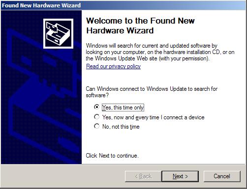
Step 1:
The wizard will ask whether or not you wish to allow Windows to connect to Windows Update to search for software. Select the first radio button: “Yes, this time only”, as illustrated in the first picture. It doesn’t really matter if you are connected to the Internet or not, because in addition, the wizard will also search (and find) the program locally on the PC. Click Next to continue.
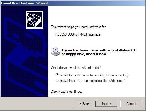
Step 2:
The wizard will inform you that the device type, for which you are about to install software, is a PD 3950. It will also ask how and from which location the software is supposed to be installed. Select the automatic method, which is the recommended choice. See the picture. Once again, click Next to continue.
The red error LED will remain lit, and both green LEDs will remain unlit.
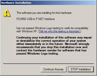
Step 3:
Now, Windows will warn about certain incompatibility problems related to the operating system. In this case, you need to trust PROCES-DATA by pressing the button Continue Anyway.
During the last seconds of this step, the green On LED will switch on, while the red Error LED will remain lit.
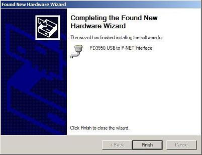
Step 4:
The software installation procedure has now been completed, and it is only necessary to click on Finish.
The green On LED remains lit, the red Error LED switches off, and the green Link LED will start flashing. This indicates that the device is communicating with the P-NET gateway service, even if VIGO is not running.
Software configuration
P-NET Gateway Service Editor
The default setting for VIGO is intended for simple PD 3950 communication. This means that if the application only involves one PD 3950, it is not necessary to run the Service Editor.
Once installed, the service starts automatically when the computer starts, so normally the user doesn’t have to be concerned about this.
When the gateway service is running correctly, the green On LED should be lit and the green Link LED should be flashing. Please consult the LED indicators for further details.
If, for some reason, the gateway service is not running correctly, or if you need to reconfigure it, you should consult the P-NET Gateway Service configuration for further details of how to proceed.
Configuration of Simple Systems
Very little knowledge is required to achieve a general understanding of the project design and to know how to make extensions to the outside world.
The MIB shown here has been built up using the most simple of the three gateway service structure types.
In the pre-configured USB project, the user doesn’t need to be concerned about some of the settings, as they have already been set. Therefore, they should be left unchanged. These are:
A single PD 3950 node is connected directly to the P-NET Gateway Service by means of a NeighbourNet. The node numbers in this point-to-point communication must be zero.
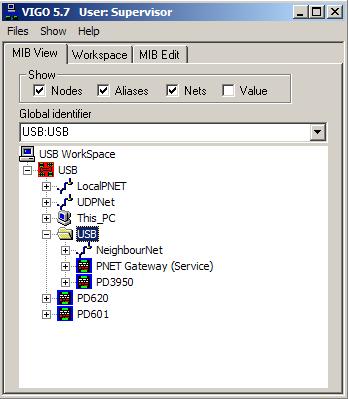
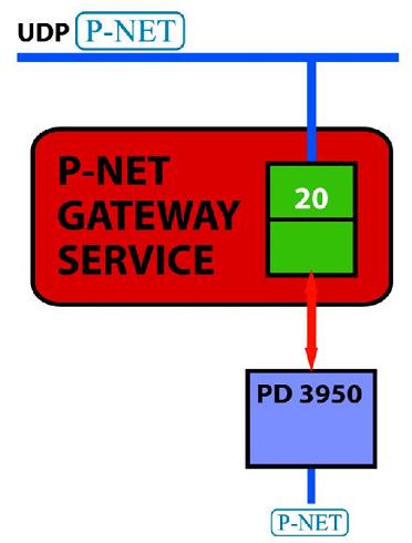
The UDPNet is an internal, non-physical Ethernet with two participants. These are ‘This_PC’ and the UPD side of the ‘P-NET Gateway Service’.
The group (folder) named ‘USB’ contains the NeighbourNet that relates the other participants, the P-NET Gateway Service and the PD 3950 to each other.
What must be considered, however, is the LocalPNET that connects the P-NET side of the PD 3950 to the modules in the application. In the default workspace, a PD 620 IO Module and a PD 600 DPI have been added as examples, as a means to indicate at which level additional modules should be positioned. They can be replaced with other modules depending on the actual requirements.
Accessing the PD 3950 and P-NET Nodes
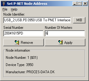
Once the configuration has been adapted to the actual requirements, the nodes on the P-NET side of the PD 3950 module must have their addresses defined.
At delivery time, the factory settings for the PD 3950 variables PnetNo and NoOMasters on the P-NET side of the module are set to zero. The resulting message when trying to access the module in this state would be ‘Port Not Master’. So, the first thing to do is to use the right-click mouse function ‘Set P-NET Node Address’ for the PD 3950. Key in the serial number of the PD 3950 and change the number of masters from zero to whatever value corresponds to how many masters are present in your local P-NET sub-net. Click Enter or Apply.
VIGO licence source
As with the PD 3930, the PD 3950 has a build-in licence for VIGO.
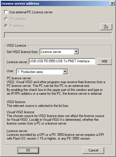
If you wish to use this licence, the PD 3950 must be selected as the licence source. Enter the VIGO menu Files \ Licence \ Licence Server. The screen picture illustrates this. Follow these instructions:
1) Leave the field ‘Use external PC Licence server’ unchecked.
2) Choose Licence server from the options in the pull-down menu ‘Get VIGO licence from’.
3) User 1 is selected automatically, since the module at delivery is equipped with only one licence.
4) The user name doesn’t need to be present. In this example, the name ‘Production area’ appears because it was keyed in previously into the module’s LicenceCh, by means of the right-click menu Channel Configuration.
The PD 3950 can also be a licence holder for Visual VIGO. Refer to our homepage to learn more about this issue.
Combining new and existing projects
If a larger and well-established system exists and works satisfactorily, you probably do not wish to recreate it in order just to introduce another method
to communicate.
On the other hand, an existing project can be changed in a way where, for example, a PD 3930 is just replaced by a PD 3950 and its related elements.
The easiest way to smoothly integrate an USB project with an existing project is to enable both of them in the relevant workspace and make a few changes. This will be explained in the following text.
Let’s have a look at the project MyExistingProject. It was originally intended for use with a PD 3930, and is therefore a nice example of how to adapt to a PD 3950. When this example is followed, your relevant project must be used instead of the MyExistingProject, but the procedures are of course the same.
How this is done
To make the relevant changes, read the explanations and follow the instructions, by replacing the example project MyExistingProject with your actual one:
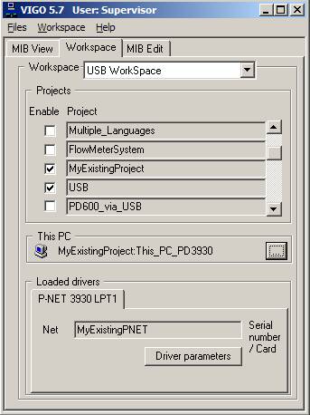
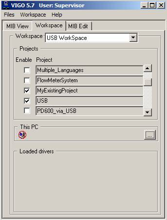
1) Select the Workspace tab and choose the workspace MyExistingProject. By means of the checkmarks, the project MyExistingProject as well as the USB project must be selected, just like the following picture indicates.
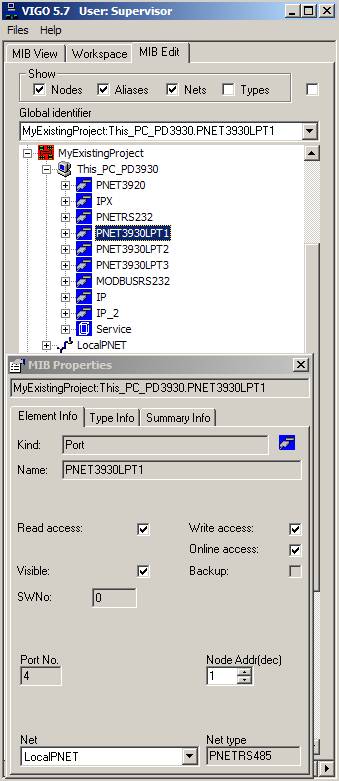
2) The next thing to do is to replace the PC of the original project with the PC belonging to the USB project. The next picture illustrates MIB Edit, in which the PC of the original project MyExistingProject has been expanded. For the port relation PNET3930LPT1, the properties window has been opened. It reveals that the net name is LocalPNET and that the node number is 1. Thus, the name of the net is LocalPNET for both projects, which is also the reason why they can be related without any changes in the net names as described. To avoid the risk of having equal node numbers for the existing participants on the P-NET side of the PD 3950 and the module itself, it is recommended to assign to the PD 3950 the node number that the PD 3930 had previously.
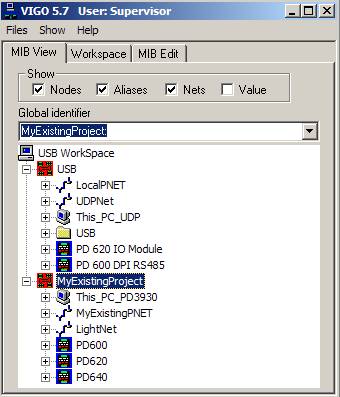
3) If the existing project has a net name that differs from the one used in the USB project (the LocalPNET), one of them must have its name changed. The screen picture illustrates such a situation. Trying to access the PD 600 leads to the error message “No route to net”, since This_PC_USB is not related to the PD 600 module. The easiest way to handle such a situation is to rename the P-NET of the USB project, assuming that it consists of a lower number of nodes than does the existing project. At the same time, you may as well use the opportunity to get rid of the example nodes PD 600 and PD 620 in the USB project. After having changed the USB net name LocalPNET to MyExistingPNET, the P-NET relation of the PD 3950 USB device must be changed accordingly.
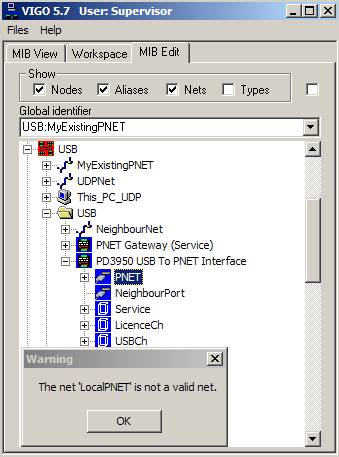
4) In the MIB Properties, the PD 3950 USB node must be related to the net with the new name, and the node must be set to the same address as the PD 3930 had in the existing project. When attempting to change it, an error message as illustrated will appear, since VIGO recognizes that the previous net no longer exists.
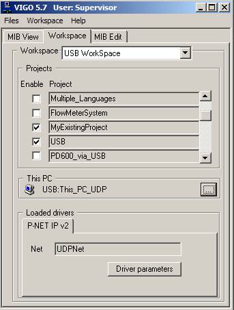
5) At this stage, the PC for communication must be selected. If This_PC in the workspace is the one that was previously selected for the MyExistingProject, it must be changed. This is shown in the This PC frame, and the loaded driver for the communication device is also listed. If no PC has been selected previously, a red symbol occurs, and the Loaded Drivers frame is blank, as shown.
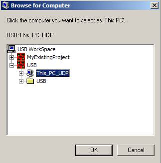
6) Click the right-hand side button with three dots, which will lead you to the menu ‘Browse for Computer’. In the browser window, open the USB project and select This_PC_UDP as indicated, and confirm with the OK button, as illustrated.
6) Click the right-hand side button with three dots, which will lead you to the menu ‘Browse for Computer’. In the browser window, open the USB project and select This_PC_UDP as indicated, and confirm with the OK button, as illustrated.
Systems with several PD 3950s
Related topics
This document has described how one PD 3950 USB interface can be installed and configured in new or existing projects.
However, in some special cases, it is required to have several PD 3950 USB interfaces installed simultaneously. In order to learn more about how to do this, please refer to the additional information, using this link: PD 3950 multiple installation